
Steel Portal Frame Buildings: Bay Spacing, Eave Height and Foundation Load Decisions

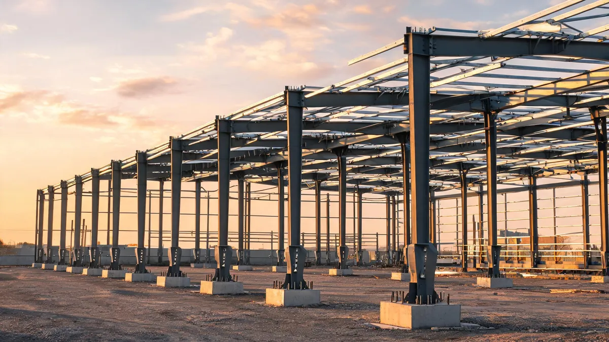
Three numbers decide more of a steel portal frame building than any other part of the brief: the bay spacing, the eave height and the base condition. Bay spacing sets how many frames and footings the building needs. Eave height sets how much wall the wind pushes against and how tall the columns have to be. The base condition decides whether the columns push, pull or rock on the foundation. Fix those three and the frame, the cladding quantities and the foundation loads follow almost automatically; leave them to the supplier to guess and you will spend the design stage arguing about a building nobody actually specified.
This guide is written for buyers and project engineers who are about to issue an RFQ for a portal frame warehouse, workshop or factory building. It explains what each grid decision changes, how the three decisions interact, and which documents have to be frozen before the civil contractor starts digging.
What a Portal Frame Building Actually Consists Of
A portal frame is a two-dimensional bent: two columns and a rafter, connected rigidly at the eaves, spanning across the width of the building. The bents repeat along the length of the building at a fixed spacing. Secondary members — purlins in the roof plane and side rails in the wall plane — carry the cladding between bents. Bracing in the roof and the walls, or the portal action of the frames themselves, takes the wind and stability forces down to the foundations.
Every variable in the drawing set traces back to the grid. That is why a supplier can price a portal frame building quickly when the grid is fixed and slowly when it is not.
| Grid variable | What it controls | Who it affects downstream |
|---|---|---|
| Span (clear width) | Rafter depth, whether internal columns are needed, roof drainage direction | Steel tonnage, foundation loads, racking or machine layout |
| Bay spacing (frame pitch along the length) | Number of frames, purlin and rail sizing, number of footings | Fabrication hours, footing count, erection crane lifts |
| Eave height | Column length and slenderness, wall cladding area, wind exposure | Base moment, bracing demand, lighting and sprinkler reach |
| Roof pitch | Rafter geometry, drainage, usable volume under the ridge | Cladding quantity, gutter capacity, solar or ventilation layout |
| Base condition (pinned or fixed) | Moment and shear transferred into the footing and slab | Anchor bolt detail, footing size, foundation cost |
Bay Spacing: The Cheapest Lever Buyers Never Touch
Bay spacing is the distance from one frame line to the next. It is usually chosen for reasons that have nothing to do with structure — door positions, racking aisles, crane runway posts, expansion joints, the length of the cladding module — and then checked by the engineer. That order is fine, as long as the consequences are understood.
Wider bays mean fewer frames. Fewer frames means fewer columns, fewer foundations, fewer base plates, fewer connections to fabricate and fewer crane picks on site. The saving is real, but it is not free: the rafters and columns have to span further between the remaining frames, and the purlins and side rails have to carry more cladding between identical supports, so secondary members get heavier and the cladding spanning capability has to be checked.
| If you widen the bay spacing… | Primary frame | Secondary steel | Foundations |
|---|---|---|---|
| Fewer frames to fabricate | Better — less repetition of the same bent | No change in length, fewer supports | Fewer footings and anchor bolt groups |
| Longer purlin and rail spans | No change | Worse — deeper or thicker sections, more rows | No change |
| Higher loads into each frame | Worse — heavier columns and rafters at each line | No change | Larger footing per column, more load concentrated |
| Crane runway between frames | Worse — runway beams span bay to bay | No change | Bigger vertical and fatigue demand on the crane columns |
| Fewer crane lifts on site | Neutral | Neutral | Neutral — but erection time usually falls |
The practical lesson: bay spacing is an economic decision with a structural bill attached, and the bill is paid in secondary steel and in the columns, not in the number of frames. Buyers who widen bays to cut the frame count often find the total steel weight barely moves, yet the erection programme shortens and the foundation count drops — which can still be the better outcome for the project even if the tonnage is unchanged.
What is a typical bay spacing for a steel portal frame building?
Single-storey portal frames are commonly laid out with bays in the 6 m to 9 m range, and 7.5 m or 8 m are popular because they divide cleanly into cladding panel widths and purlin spacings. Wide, tall, lightly loaded roofs can justify bays beyond that; short buildings with overhead cranes, heavy suspended services or a requirement that every frame line coincides with a racking or process grid usually stay at the lower end. Treat the range as a starting point for the design conversation, not as a rule — the correct bay spacing for your building is the one that satisfies your layout and then passes the structural check.
Two layout details are worth locking in early because they are painful to change later. First, the position of every door, roller shutter and personnel opening should coincide with a bay rather than straddle a frame line, so the portal does not have to be broken twice. Second, if the building may be extended by adding bays at one end, say so before the first drawings are issued; an extension gable designed from the start costs far less than one retrofitted later.
Eave Height: The Decision Buyers Underestimate Most
Eave height is measured at the top of the wall, where the wall meets the roof line. It is not the same as the clear height inside the building, and confusing the two is one of the most common sources of late variations.
Raising the eave height changes four things at once. The wall area grows, so there is more cladding, more side rails and more insulation. The column gets longer, so it is more slender and its buckling behaviour changes. The wind pressure on the wall grows with height above ground, so the horizontal load on the frame rises even though the plan area has not changed. And the lever arm between the base and the point where wind acts on the frame lengthens, which increases the moment at the column base and therefore the demands on the footing and anchor bolts.
| Change | Frame effect | Envelope effect | Foundation effect |
|---|---|---|---|
| Eave height increased by roughly one metre | Longer, more slender columns; higher base moment | More wall cladding, rails and insulation per metre of perimeter | Higher horizontal reaction and base moment; deeper or larger footing |
| Clear height increased while eave stays the same | No change to the frame | No change | No change — but check purlin depth, sprinkler and lighting obstructions |
| Pitched roof retained, ridge raised | Rafter geometry changes; ridge member and bracing affected | Roof area grows slightly with pitch | Minor change in vertical load, no change in plan foundations |
| Monoslope converted to gable | Frame becomes symmetric; different wind cases govern | Gutter and downpipe arrangement changes | Reaction pattern changes between columns |
Eave height or clear height — which one belongs in the RFQ?
Put both in the RFQ, and define what you mean. The clear height is the usable vertical space inside: under the lowest obstruction, which is usually the bottom of the haunch near the column, the underside of a service or sprinkler pipe, or the lowest point of the rafter for a building without a ceiling. When you buy a forklift or a stacker, the number that matters is the free lift plus the load plus a working clearance, and the number the structure cares about is the eave height. A supplier who receives a clear height alone will estimate the eave and may estimate it on the low side, which leaves you re-quoting after the shop drawings arrive.
Two rules of thumb help in early planning, and both should be confirmed against your supplier’s drawings. First, purlins, sprinkler mains, lighting and ductwork all steal vertical space beneath the rafter, so plan the clear height above the highest rack or the highest machine, then add an allowance for those services rather than assuming the structure stops being in your way at the eave. Second, if the building has a mezzanine, the eave height is driven by the space required over the mezzanine floor, not by the ground floor requirement, and that is a conversation to have before the frame layout is fixed.
Does a taller eave always cost more?
For the same footprint, plan the taller building as the more expensive one, but the increase is not proportional. The cladding and side rails grow roughly with the wall area, the columns grow more steeply because slenderness affects their design, and the foundations grow only where the increased moment demands it. The one case where a taller building is close to cost-neutral is when the change is small and the column was previously governed by an unrelated load case such as a crane or a heavy ridge unit. Ask your supplier to quote the height you actually need rather than accepting a standard height because it is common — and ask what changes if you add or remove 500 mm.
How Bay Spacing and Eave Height Become Foundation Loads
The structural engineer working for the supplier does not design the foundation. The supplier designs the frame and issues the reactions at the column base: a vertical load, an uplift where wind suction exceeds the gravity load, a horizontal force in the plane of the frame and a base moment if the connection is not a simple pin. Those numbers are the interface between the steel package and the civil package, and everything about the footing, the anchor bolts and the slab follows from them.
The load path is short and worth following once. Roof and wall cladding loads reach the purlins and rails, which deliver them to the rafters and columns. The frame carries them down to the base plates. If the base is pinned, the frame sheds the horizontal force into the bracing system and the base transfers mainly vertical load and shear. If the base is fixed, the base plate and its anchor bolts must transfer a bending moment as well, which means a heavier base detail and a footing designed to resist rotation.
| Base condition | What the base transfers | Typical anchor bolt implication | Foundation implication |
|---|---|---|---|
| Pinned base | Vertical load, uplift, shear — little or no moment | Fewer, smaller bolts arranged for shear and tension | Simpler pad footing; stability provided by bracing or portal action |
| Fixed base | Vertical load, uplift, shear and a bending moment | More or longer bolts, larger base plate, often stiffeners | Footing sized for moment — larger, deeper, more reinforcement |
| Base tied into a slab-on-grade | As above plus interaction with the slab | Bolts cast into the footing, not the slab | Slab must be detailed so it does not act as an unintended tie |
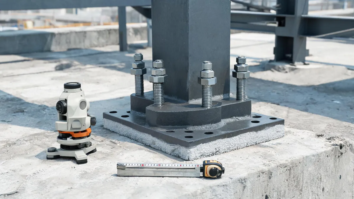
Two project decisions flow from this table. First, whoever designs the foundation needs the reaction schedule early — not the final shop drawings. A preliminary reaction set is enough to size footings and order concrete, and waiting for the final set costs programme time without buying much accuracy. Second, the anchor bolt setting plan and the footing drawing must be prepared by the same team or coordinated by one party. When the steel supplier sets bolts to one layout and the civil contractor pours to another, the result is a variation order, a site-fabricated base plate and an argument about who pays.
Who provides the foundation loads, and who checks them?
The steel supplier’s engineer provides the reactions and the anchor bolt plan. A local engineer — required in most markets for the building permit — designs the footing and the slab using the local soil report and the local code, and signs the submission. The two documents must be compared line by line before concrete is poured: bolt diameter and grade, bolt projection above the concrete, edge distance, grout thickness and the design level of the top of the footing. In export projects this comparison is the single most valuable hour of engineering time in the whole package, because fixing an anchor bolt after the footing is cast is a site-welding problem with a permanent engineering consequence.
Reading the Three Decisions Together
Individually, each decision looks reasonable. Together they determine whether the building you receive is the building you budgeted for. The table below shows how a change in one column ripples through the others, which is the argument for freezing the grid before the RFQ rather than during the design.
| Decision you change | What it forces you to re-check | Contract implication |
|---|---|---|
| Widen the bay spacing | Purlin and rail sizes, crane runway posts, cladding spanning, each frame’s load | New shop drawings and often a new quotation for secondary steel |
| Increase the eave height | Column design, base moment, wall cladding, bracing, lighting and sprinkler reach | Variation to the frame price and possibly to the footing design |
| Move a column line | Anchor bolt positions, footing layout, slab joints, door positions | Civil variation; the most expensive grid change a project can absorb late |
| Switch from pinned to fixed base | Column design, base plate and bolt detail, footing size and reinforcement | Design-stage change with a clear cost, but manageable before concrete |
| Add an overhead crane | Column section, crane beams, base loads, fatigue considerations | Structural redesign of the affected bays and their footings |
Sequencing: Grid Decisions Have Deadlines
The grid is not an abstract drawing exercise; it has a date attached to it, because the foundation is built before the steel arrives. In a typical export project the order runs like this: site survey and soil report, preliminary grid agreed, reaction schedule issued, foundation drawings prepared and approved, footings cast, anchor bolts verified, steel shipped, frame erected. The anchor bolt verification step is the last chance to correct a mismatch cheaply, and it happens weeks before the frames reach the port.
Builders who manage this well treat the grid as frozen at the moment the foundation drawings are issued. Everything after that is a variation with a price. If your project will also need worker accommodation, a site office or a canteen during construction, plan those facilities at the same time as the civil works — modular units are usually delivered and positioned quickly, and separating them from the main structural procurement keeps the critical path on the permanent building. A container house supplier, for example, can provide site offices and welfare units that do not interfere with the steel package or its tolerances. That parallel route keeps site facilities off the critical path without adding scope to the frame contract.
One more sequencing point that catches international buyers: the steel package and the civil package are often awarded to different companies in different countries. Somebody has to own the interface. If nobody does, the responsibility for reconciling the reaction schedule with the footing design falls into the gap between two contracts, and that gap is exactly where anchor bolt errors are born. Write the interface into one of the two scopes — usually the steel supplier, because the reactions are theirs — and require a signed comparison before the first pour.

What to Send in the RFQ So the Grid Comes Back Right
A portal frame quotation is only as good as the grid behind it. Buyers who send a complete brief receive a firm frame price; buyers who send a footprint sketch receive a placeholder that changes three times before it becomes real. Include these items in the first inquiry:
| RFQ item | What to state | Why the supplier needs it |
|---|---|---|
| Overall dimensions | Length, span or spans, and whether internal columns are acceptable | Decides the rafter depth and the roof framing scheme |
| Bay spacing | Preferred pitch along the length, or the layout constraint it must follow | Sets frame count, purlin design and footing count |
| Eave height and clear height | Both numbers, with the clear height defined under the lowest obstruction | Separates the structural decision from the operational one |
| Roof pitch | Minimum acceptable pitch, or the drainage requirement | Affects geometry, cladding choice and gutter sizing |
| Site location and loads | City and country, plus any known wind speed, snow load or seismic requirement | Sets the design cases that govern member sizes |
| Base preference | Pinned or fixed, or leave it to the engineer with a note that the foundation is separate | Determines the reaction schedule the civil team will receive |
| Doors and openings | Every opening with size, position and type, aligned to the bay grid | Avoids breaking frames twice and re-working the wall rails |
| Cranes and suspended loads | Capacity, span, duty class and runway height if any | Changes the column design, crane beams and base loads |
| Supply scope and delivery | Supply-only or with erection, plus the Incoterm and destination port | Keeps quotes comparable and clarifies who builds the foundation |
The quote requirements page on this site lists the same information in the order a factory actually needs it, and it is worth reusing as an internal checklist so no item is dropped between departments.
Six Mistakes That Cost Real Money on Portal Frame Projects
- Fixing the bay spacing after the foundation is designed. The footing positions follow the frame lines. Moving a line after the pour means new bolts, new base plates and a site welding operation that no engineer wants to sign.
- Buying clear height and assuming eave height. The difference is eaten by purlins, services and the haunch, and it is discovered on the drawing review rather than in the business case.
- Leaving the base condition undefined. A supplier who assumes a pinned base prices a lighter frame and a simpler footing than a fixed base design requires. Ambiguity here produces two quotes that cannot be compared.
- Sending the reaction schedule after the concrete is poured. The civil contractor needs preliminary reactions early. Late reactions are only useful for the next building.
- Aligning racking or process lines to a nominal grid. If the real grid differs by a few centimetres, every racking leg, conveyor support and machine base inherits the error. Confirm the as-built grid before ordering the fit-out.
- Treating the gable as decoration. The gable frame, its wind posts and its bracing carry the end-wall loads. Reducing them to save cost is a structural decision, not a detailing one.
There is a seventh mistake worth mentioning because it is invisible in the price: buying a frame optimized to the last kilogram without checking the foundation that comes with it. A lighter frame usually means more deflection and larger base moments in a given geometry, and the footing may cost more than the steel saved. Ask for the reaction schedule and the steel weight together, and compare the pair rather than the tonnage alone.
How the Grid Shows Up in the Quote and the Programme
Because the grid drives the quantities, it also drives the price direction — even though no honest supplier can give you a per-square-metre rate before the grid exists. Widen the bays and you should expect the primary frame weight per square metre to move slightly up, the number of footings and base plates to fall, and the erection programme to shorten. Raise the eave and expect more wall area, longer columns and a heavier base detail. Fix the base and expect a heavier base plate and footing but a lighter column. These are directions, not percentages; the actual numbers depend on span, load case and the code you build to.
The programme effects are easier to predict and often more valuable than the cost effects. Fewer frames means fewer crane picks, fewer bolt-up operations and fewer alignment corrections, all of which compress the erection phase on site. A building with wide bays and a light roof can be far quicker to erect than a building with narrow bays and the same tonnage, which matters when site labour and crane hire are the expensive items in your budget.
A Decision Sequence That Works
- Define the operation first. Racking heights, forklift or crane movement, process equipment, offices and future expansion set the minimum span, clear height and door layout.
- Choose the bay grid to suit the operation, then check it against cladding and purlin module lengths.
- Convert clear height into eave height with your supplier, allowing for purlins, services, lighting and the haunch depth.
- Decide the base condition with the engineer, and record who designs the footing and who signs the approval documents.
- Freeze the grid and issue the RFQ with the load information, opening schedule and supply scope included.
- Require the reaction schedule and anchor bolt plan before the foundation drawings are finalized, and compare the two documents in writing.
- Verify the as-built bolt positions and levels before erection starts, with a recorded survey rather than a visual check.
Before the RFQ goes out, it is worth reading the guides already on this site that cover the two interfaces this article touches: anchor bolt plans and foundation data for what the supplier must issue at the base, and foundation coordination for buyers for how the civil and steel packages should be stitched together. If your project has to work to a specific wind or snow case, the site’s wind load design notes explain how the basic wind speed translates into the pressures the frame is designed for. And if you are still comparing frame types, truss versus portal frame covers the choice that sits one step above the bay grid. Buyers who have not yet fixed the overall size should start from the prefab steel warehouse range and work backwards to the grid from there.
Frequently Asked Questions
What is a typical bay spacing for a steel portal frame building?
Most buildings use bays between 6 m and 9 m, with 7.5 m and 8 m common because they suit standard cladding and purlin modules. Widen the bays when the roof is lightly loaded and the building is tall, and keep them tighter when there is an overhead crane, heavy roof equipment or a racking grid the frames must match.
Does eave height affect the foundation design?
Yes. A taller eave increases the wall area exposed to wind and lengthens the lever arm from the base to the point where that wind acts, so both the horizontal reaction and the base moment usually rise. The footing has to be designed for the result, which is why the eave height should be fixed before the foundation drawings are issued.
Who is responsible for the foundation loads of a portal frame building?
The steel supplier issues the column reaction schedule and the anchor bolt setting plan. The local engineer designs the footing, the slab and the connection to the structure, and signs the permit submission. Both documents must be compared before the first pour, and one party should own that comparison in the contract.
Should the base of a portal frame column be pinned or fixed?
A pinned base is the common default because the footing and the bolt detail stay simple, with stability provided by bracing or portal action. A fixed base reduces bending in the column and can allow lighter members, but needs a heavier base plate, more anchor bolts and a footing designed for moment. Decide it during design, not on site.
What happens if the bay spacing changes after the foundation is built?
It turns into a variation. New column positions require new anchor bolts, which usually means breaking out or re-casting part of the footing, plus revised shop drawings, new base plates and a fresh approval cycle. Freeze the grid before the foundation drawings are issued and price any later change honestly.
Ready to fix the grid and get a real number? Send us the span, bay spacing, eave and clear height, site location, door schedule and any crane details, and our engineering team will return a frame design with the column reaction schedule so your civil contractor can design the foundation in parallel. Start with the prefab steel warehouse range, or request a quotation with your project brief and we will confirm what the drawing set will contain before you sign anything.