
Portal Frame Structure Design: Key Load Data and Specifications for Prefab Buildings

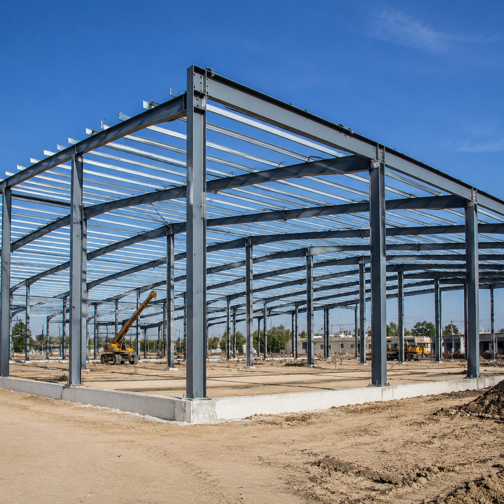
Portal frame structure design determines the span capacity, load resistance, and total installed cost of prefab steel buildings. For construction buyers and general contractors, the primary frame is not just a proportioning exercise — it defines the building’s safety, serviceability, and ease of erection. This article condenses the key structural specifications, load data, standards, and installation factors you need to review before ordering a portal-frame steel building.
Core Elements of Portal Frame Structure Design
A portal frame consists of rigidly connected steel columns and rafters that, together, resist vertical and lateral loads by frame action. Unlike simple post-and-beam structures, the portal frame uses moment connections at both the eave and the ridge; these joints transfer bending moments as well as axial and shear forces, and the column bases are usually designed as pin or fixed supports.
Key geometric parameters a buyer normally defines:
- Span (column center to column center), commonly 12 m to 40 m
- Eave height, from 4 m to 12 m or higher for large lifting equipment
- Column spacing (bay spacing), typically 6 m, 7.5 m, or 9 m
- Roof slope, usually 5° to 10° for drainage and interior clear height
- Number of bays and presence of internal columns for multi-span frames
The primary members (columns and rafters) are usually welded H-sections or hot-rolled I-sections. The secondary structure includes roof purlins, wall girts, and eave struts, normally cold-formed C- or Z-sections, which support the roof and wall sheeting. Diagonal bracing (roof cross-bracing and wall bracing) plus tie rods transfer longitudinal loads back to the primary frames. Material grades commonly specified include Q235B/Q355B for domestic Chinese projects, and ASTM A572 Gr. 50 or S355 equivalents for international projects.
For buyers, the most practical check when reviewing a design: confirm that the primary member schedule lists section size, length, steel grade, and quantity of each column and rafter, and that the connection detail around the haunch and base plate matches what your engineer of record approves.
Load Data and Design Standards That Drive a Safe Frame
Load data is the part of portal frame structure design that separates a good quotation from a dangerous one. Your building supplier must know the following design inputs:
- Dead loads — self-weight of the steel frame, cladding, insulation, roof panels, services, and any suspended equipment.
- Live load — maintenance load on the roof, often 0.3 to 0.5 kN/m² depending on the applicable code.
- Wind load — calculated from the basic wind pressure or basic wind speed at the project location, terrain category, building height, and roof pitch. Wind uplift on the roof and suction on walls often govern member sizes.
- Snow load — ground snow load converted to roof snow load using shape coefficients that depend on the roof slope.
- Seismic load — for moderate to high seismic zones, lateral forces depend on spectral acceleration, building mass, and ductility of the frame.
- Crane load — if an overhead crane is required, the designer must include vertical wheel loads, longitudinal braking force, and transverse crane surge. A building designed for a 5 t crane is not interchangeable with one designed for a 20 t crane.
The design is generally based on limit-state principles: ultimate limit state for strength and stability, and serviceability limit state for deflection and drift. Typical limits include roof deflection of L/180 to L/240 under live load, and frame side sway controlled by crane class when a crane is present.
Commonly used codes include GB 50017 and GB 50009 (China), AISC 360 (USA), EN 1993-1-1 (Eurocode 3), and JIS standards for certain Asian markets. Confirm the governing code at the quotation stage, because it defines the load combinations and safety factors. A reliable supplier will include a load-case summary showing the basic wind pressure, ground snow load, and seismic parameters used for your specific project location.
What to Check in Shop Drawings and Connection Details
Before fabrication, the supplier will issue shop drawings. These drawings must match the calculation model and the project’s requirements, not just represent a standard frame that the factory prefers to produce.
- Member sizes and connection details match the approved structural model.
- Base plate dimensions and anchor bolt hole locations align with the foundation drawings issued to the civil engineer.
- High-strength bolt grades and connection types match the moment capacity assumed in the design.
- Weld sizes and symbols, including full-penetration versus fillet welds, are clearly marked.
- Coating system is specified correctly: hot-dip galvanizing for coastal or high-humidity environments, or epoxy paint for inland projects.
- Hole positions are coordinated with CNC drilling to avoid on-site rework.
If the erection team re-drills or enlarges holes for high-strength connections, the joint slip resistance can be seriously reduced. A proper portal frame structure design depends on precise hole coordinates and full preload in the bolts. Ask the supplier to include the primary-frame calculation report in the technical submission; this allows your local engineer to verify the design assumptions and confirm that the section sizes are adequate for your site conditions.
Delivery and Installation: How Design Affects Assembly
A portal-frame steel building is delivered to site as loose members, not as a pre-assembled frame. Columns and rafters are typically shipped in groups, with purlins and bracing nested together to optimize container space. Because column and rafter lengths can range from 6 m to 14 m, delivery planning must account for trucking permissions, container size limits, and unloading equipment at the project site.
Installation sequence, simplified:
- Verify anchor bolts against the supplied foundation layout before lifting any steel.
- Erect the first bay’s columns on the anchor bolts and support them with temporary guys.
- Set the rafters and assemble the eave and ridge connections.
- Align the frame plumb and square the bay.
- Tighten high-strength bolts to the torque specified for the friction joint.
- Install purlins, girts, and permanent bracing.
- Fix roof and wall cladding, flashings, and gutters.
An experienced erector will follow the erection manual supplied with the drawings. The frame is stable only when the specified bracing and connections are in place, so temporary supports must remain until permanent bracing is installed. Structural integrity is a combined result of correct member design and correct field assembly.
FAQ 1: How can I verify that the portal frame design meets my site’s wind and snow loads?
Provide your local code parameters at the inquiry stage: basic wind pressure or wind speed, ground snow load, and seismic zone. When you receive shop drawings, check the load-case summary against those same values. If the inputs match and the governing load case is stated, the design is consistent with your permit application. Ask the supplier to provide the calculation report and have a locally licensed engineer review it before you approve fabrication.
FAQ 2: What common field mistakes weaken a portal frame?
The most frequent problems are under-torqued high-strength bolts, which turn a moment connection into an unintended pinned connection; removing temporary guys before permanent bracing is installed; and re-drilling holes on site, which enlarges bolt holes and reduces slip resistance. Make sure the erector follows the installation sequence, torque table, and bracing layout included in the erection manual.