
Portal Frame Structure Design: Specs, Load Data, and Standards

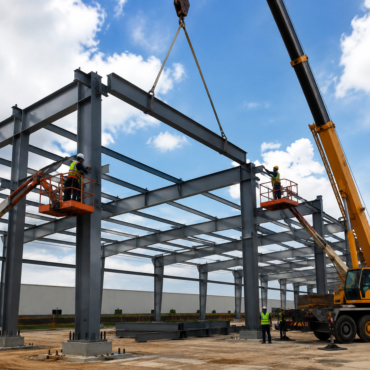
Portal frame structures are one of the most economical steel building systems for industrial and commercial projects. From distribution warehouses to manufacturing workshops, the rigid moment-resisting connections of a portal frame allow long clear spans without internal columns. For construction companies and project buyers, understanding the design logic behind these buildings is essential for cost control, foundation planning, and smooth site installation. This article explains the main structural specifications, load data, engineering standards, and the typical delivery and erection workflow.
Portal Frame Structural Specifications
A portal frame is a rigid steel frame made from hot-rolled H-sections or welded plate sections. The primary structure consists of columns, which support vertical loads, and rafters, which form the roof slope. These members are connected with moment-resisting joints so that the frame responds to wind, snow, and crane loads as a single structural unit.
The design parameters shown below are typical, but should always be confirmed by a structural engineer for each project:
- Clear span. Single-span portal frames commonly span 12 m to 48 m. Wider clear spans are possible with larger sections or by adding intermediate columns for multi-span layouts.
- Eave height. Standard eave heights are usually 4 m to 12 m. Buildings with overhead cranes or tall racking can require heights above 12 m, which increases column and foundation sizes.
- Roof pitch. Most portal frames use a 5 to 15 degree pitch. Low pitches reduce the building envelope volume and cladding area, but require careful rainwater drainage design.
- Bay spacing. Frames are typically spaced at 6 m to 9 m centres. Larger bay spacing lowers the number of frames but increases the size of rafters, purlins, and foundation loads.
- Secondary steel. Cold-formed C- or Z-section purlins support the roof panels, and girts support the wall cladding. Typical spacing is 1.2 m to 1.5 m.
- Bracing. Longitudinal stability is provided by cross-bracing in the roof and walls. The transverse direction is resisted by the portal frame action itself.
In practice, designers use optimization software to balance member sizes, total weight, and fabrication cost. The final frame layout is a compromise between architectural requirements, material efficiency, and site conditions.
Load Data and Design Considerations
Every portal frame must be designed for the combinations of loads that can act simultaneously during its service life. The key load categories are:
- Dead loads: self-weight of steel members, cladding, insulation, gutters, and permanent services.
- Imposed (live) loads: maintenance personnel, roof access equipment, and suspended loads. Roof live loads often range from 0.25 kN/m² to 0.60 kN/m², depending on the design standard and access level.
- Snow loads: determined by climate zone, roof slope, and elevation. Drifting snow at steps and parapets must also be checked.
- Wind loads: calculated from the local basic wind speed, terrain category, and building geometry. Wind uplift on the roof and high positive pressures on large wall panels often control the design of purlins and holding-down anchors.
- Seismic loads: in earthquake zones, the frame must have sufficient ductility and stable energy dissipation. Connection details and bracing systems follow the local seismic code.
- Crane loads: if the building includes a bridge crane, vertical wheel loads, side thrust, and braking forces are included in the frame analysis and fatigue checks.
Structural designers combine these loads using the strength and serviceability combinations specified by the project standard. Common serviceability limits are rafter deflection of span/180 to span/240 under live load, and column drift of height/150 to height/300 under wind, depending on the type of cladding. Excessive deflection can cause roof ponding, cladding damage, and door misalignment, so these limits are not just aesthetic.
Load data must always come from the site-specific meteorological report, geotechnical investigation, and the client’s functional requirements. There is no universal load table; the same building shape can have significantly different member sizes in different environments.
Fabrication, Delivery, and Installation Sequence
The process from order to handover follows a logical order. Understanding it helps buyers coordinate foundation works, crane availability, and labor on site.
The typical sequence is:
- Shop drawings: the structural engineer prepares detailed fabrication drawings, which are approved by the client and the engineering consultant before production starts.
- Fabrication: CNC cutting, drilling, welding, and assembly of columns, rafters, base plates, and connection plates. Members are then shot-blasted and painted to the specified corrosion-protection system.
- Delivery: the frame is transported as a knocked-down package with all bolted connections. Knocked-down transport reduces truck volumes and protects the surface coating during transit.
- Foundation coordination: anchor bolts are cast in position according to the base-plate drawing. The delivery schedule should align with concrete curing time and bolt-position tolerances.
- Erection: crews assemble columns and rafters into frame units on the ground, then lift them into position with a mobile crane. Temporary bracing secures each frame until permanent bracing and torque-controlled bolting are completed.
- Envelope installation: purlins and girts are fixed, followed by roof and wall cladding, flashings, and accessories such as gutters and downpipes.
Good site communication reduces downtime: the erection team should know the lifting weight of each frame, the required crane radius, and the order of frame delivery. Quality checks occur at every stage, from joint fit-up during fabrication to bolt-torque verification on site.
Frequently Asked Questions
What are the typical spans and heights for portal frame structures?
Single-span portal frames commonly achieve clear spans from 12 m to 48 m, with eave heights from 4 m to 12 m. Multi-span buildings can extend much further, and special handling equipment may require higher eaves. The structural engineer selects final dimensions based on the client’s process needs, local wind and snow loads, and foundation conditions.
Which design standards apply to portal frame structures?
The applicable standards depend on the country and site. In North America, ASCE 7 and AISC 360 are frequently used; in Europe, Eurocode 3 (EN 1993-1-1 and EN 1993-1-8); and for many projects in China, GB 50017 and GB 51022. Local codes may add seismic, fire-resistance, or wind requirements. A licensed engineer must confirm the governing standard before finalizing the design.