
Steel Workshop Construction: Structural Specs, Load Data, and Installation

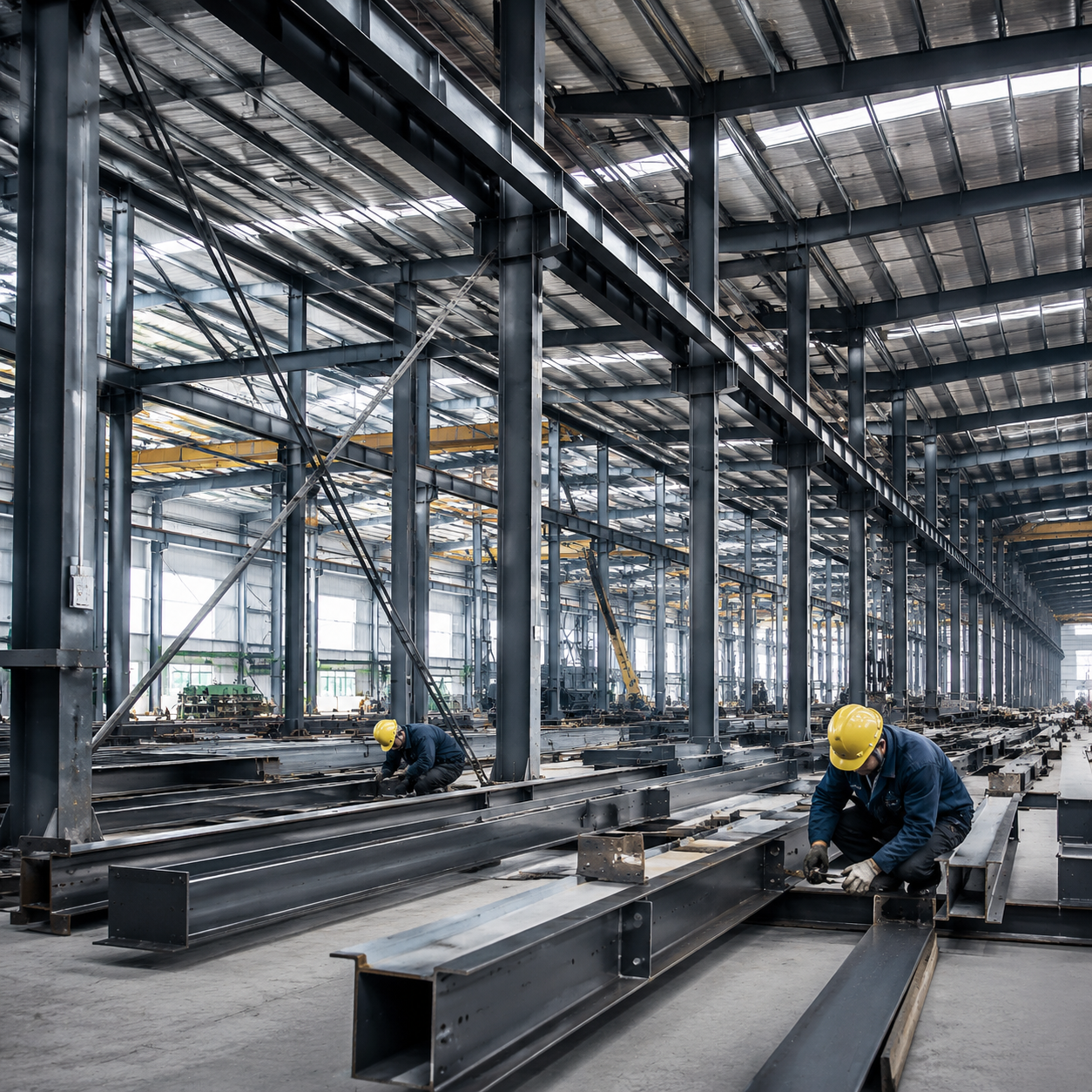
For construction companies and project buyers, planning a steel workshop building requires more than deciding on a shape and size. A well-designed steel workshop balances structural performance, logistical feasibility, and installation efficiency. This article focuses on the core technical details that affect procurement and site work: primary frame specifications, load data, commonly referenced design standards, and the step-by-step sequence from foundation to cladding. It is written for those who need practical decision-making information rather than generic sales messaging.
Core Structural Specifications for Steel Workshops
Most modern steel workshops are built with a portal rigid frame system. This configuration offers large clear spans without interior columns, which is ideal for storage, production lines, or vehicle access. The primary frame consists of hot-rolled or built-up I-section columns and rafters, connected with high-strength bolts or welded splices at the factory. For sourcing teams, the following parameters typically define the structure:
- Clear span width: commonly ranges from 12 m to 36 m. Spans beyond 36 m are possible but require heavier sections and more complex transport arrangements.
- Column spacing (bay length): usually 6 m, 7.5 m, or 9 m. Tighter spacing reduces the size of roof purlins and wall girts, while wider spacing lowers foundation count but increases frame weight.
- Eave height: typically 4 m to 12 m. Taller eaves are required for overhead cranes or multi-level mezzanines, so confirm clear height under crane hooks if applicable.
- Roof pitch: typically 5% to 10% for proper drainage. Low-slope roofs need careful sealing and insulation detailing.
- Secondary members: cold-formed C or Z purlins and girts, spaced 1.0 m to 1.5 m apart, support the cladding and transfer wind loads to the main frame.
- Bracing systems: rod or angle bracing in the roof and walls provides longitudinal stability. In seismic or high-wind regions, engineers may add knee braces or moment connections.
For projects that include suspended overhead cranes, the structural design must specifically account for crane rail reactions. The crane girder brackets are welded to columns, and the column section is enlarged to resist moments from both the crane and the building roof. Always provide the crane manufacturer’s load profile to the steel supplier before detailing begins.
Load Data and Design Standards
Every steel workshop is engineered to resist specific loads. Buyers should expect the design to follow recognized international or national standards, such as ISO, EN, GB, or AISC guidelines. The actual load values depend on the project site, not on the steel supplier’s preference. The key load types are:
- Dead loads: self-weight of the steel frame, cladding, insulation, roof panels, and all permanently attached equipment.
- Live loads: loads from maintenance personnel, tools, and temporary items on the roof. Common rooftop values are 0.3 to 0.5 kN/m², depending on access requirements.
- Wind loads: calculated from local basic wind speed, terrain category, building height, and roof pitch. Wind pressure acts on walls and roof as positive or negative (suction) loads.
- Snow loads: based on regional snow depth and roof shape. For flat or low-pitched roofs, snow drift at parapets or valleys must be considered.
- Seismic loads: in earthquake zones, the design must comply with the response spectrum or equivalent static method. Steel frames are usually ductile but need proper connection detailing to avoid brittle failure.
- Crane loads: vertical wheel loads, crane girder self-weight, longitudinal braking forces, and lateral surge forces if an overhead crane is installed.
Load combinations follow the principle of “ultimate limit state” and “serviceability limit state” checks. This means the frame is designed so it will not collapse under worst-case combined loads, and also will not deflect excessively under normal working loads. Common serviceability limits are: frame drift under wind ≤ H/150 or H/200, roof deflection under live load ≤ L/180 to L/240, and crane runway beam deflection ≤ L/600 or L/1000 for high-duty cranes.
When reviewing a structural drawing package, verify that the design loads are clearly marked and that the steel supplier provides a calculation report signed by a licensed structural engineer in the project’s jurisdiction. Do not rely on “one size fits all” drawings from previous projects, since local wind and seismic conditions vary greatly.
Delivery, Foundation Interfaces, and Installation Sequence
A steel workshop is usually delivered as bolt-together components, cut and drilled at the factory. This reduces field welding and speeds up assembly. However, delivery and installation require close coordination with civil works. The sequence below is typical for a prefabricated steel workshop:
- Foundation and anchor bolts: Before steel arrives, the concrete foundation must be cured and checked. Anchor bolt positions, projection length, and levelness are verified against shop drawings. The tolerance for bolt spacing is usually no more than ±3 mm.
- Column erection: Columns are lifted into place using a mobile crane, aligned to grid lines, and temporarily guyed. Field splice connections for column bases use nuts and washers over anchor bolts, then the base is grouted with non-shrink grout.
- Main frame assembly: Rafters (roof beams) are connected to column tops. In multi-span buildings, interior columns are erected first, then exterior frames are tied with roof purlins to maintain stability. High-strength bolts in friction connections must be tensioned to the specified pretension load using a torque wrench or turn-of-nut method.
- Secondary members and bracing: Purlins, girts, and wind bracing are installed to stabilize the frame and provide support for cladding.
- Roof and wall cladding: Sandwich panels, insulated panels, or corrugated steel sheets are fixed with self-drilling screws and sealing washers. Flashings and ridge caps are installed to ensure weather tightness.
- Crane rails and final fit-out: If the workshop has a crane, the rails are aligned and grouted, then the crane can be positioned. Doors, ventilation, gutters, and electrical conduits are completed during the final phase.
For delivery planning, note that standard sea or rail containers accommodate members up to 12 m long without special handling. Longer rafters shipped in one piece require low-bed trailers and access roads wide enough for turning. For remote sites, consider a CGI or knotless roof panel layout that reduces cutting and waste.
Installation crews should have proper lifting equipment, fall protection, and site supervision. The erection plan must account for wind speed limits (typically no erecting when wind speeds exceed 10–12 m/s), and temporary bracing must remain in place until the frame is fully aligned and bolted. A practical rule of thumb: a 2,000 m² steel workshop with clear height of 8 m can take 4–6 weeks to erect with a crew of six to eight, assuming good foundation readiness and weather conditions.
Frequently Asked Questions
What foundation preparation does a steel workshop require?
Steel workshops are often erected on reinforced concrete strip footings or isolated pad foundations, designed based on the soil bearing capacity and column axial loads. The concrete pour includes embedded anchor bolts, which must match the steel shop drawing exactly. If the soil is poor, a raft foundation or pile foundation may be required under the entire building. Ensure the foundation top surface is level and cured sufficiently before steel delivery; many suppliers offer a foundation diagram with bolt patterns as part of the technical package.
How long does installation typically take for a prefabricated steel workshop?
Installation time depends on project size, site access, crew experience, and weather. For a typical small workshop of 500–800 m², fabrication takes 3–4 weeks and on-site erection can be completed in 1–2 weeks. A larger 2,000–3,000 m² building with an overhead crane may need 2–3 months total from order to handover, including drawings, fabrication, shipping, and erection. Always add a buffer for foundation curing and unexpected site conditions.